

Tilt Beam
![]()
![]()
*COMPATIBLE WITH BOTH FLATMESH™ AND GEOWAN™ SYSTEMS*
The Tilt Beam is a lightweight, rigid aluminium beam that is used in conjunction with a Triaxial Tilt Node or a Nano Plus. The beam can be mounted in any orientation and rapidly deployed in single and daisy chained configurations.
Installation of the Tilt Beam can be performed with minimal tools in minutes. Complex bolting and washer arrangements are not required due to the beam’s inbuilt bearing and joint system. This allows for thermal expansion and misalignment of the support brackets while still accurately monitoring the structure. The attached tilt node does not require any levelling, further reducing onsite installation time.
It has been successfully used in many applications, including those measuring:
• Movement monitoring of any structure
• Longitudinal settlement
• Tunnel convergence/divergence
• Lateral displacements
key Benefits
• Lightweight and durable aluminium and stainless-steel construction.
• Fully wireless; no wiring or electrical connections required.
• Simple installation and removal. Brackets install in minutes. Beam installs in seconds.
• Can be installed in any orientation without requiring levelling.
• Low friction, weather resistant bearings that do not require maintenance or lubrication.
• Automatically compensates for thermal expansion and misalignment of support brackets.
• Can be daisy chained to provide movement profiles.
Physical Specifications
| Node Part No. | Bracket Part No. | Description | Battery Life |
|---|---|---|---|
| FM3N-IX | FF-MP-S360 | FlatMesh Triaxial Tilt Node | 12-15 years |
| FM3NT-30 | FF-BM30 | FlatMesh Nano Plus Node | 4-5 years |
Vertical Range

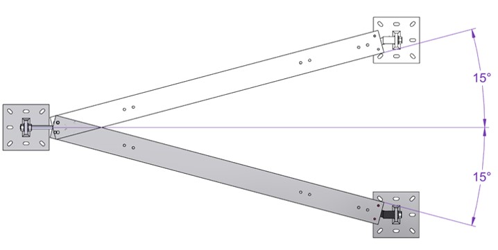
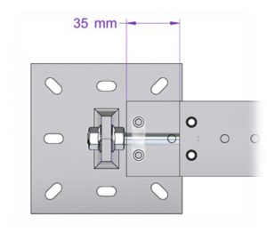
Expansion Range
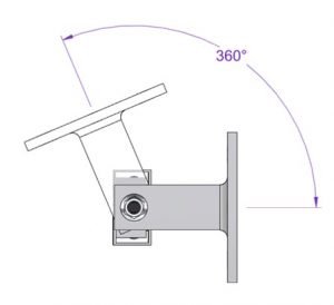
Rotational Range
Ordering
Step 1 – FlatMesh Tilt Beam:
Beam length is specified using the part numbers below. The length refers to the distance between the support bracket centres.
| Parameter | Value |
|---|---|
| Dimensions excluding antennas | 218 x 68 x 126 mm |
| Dimensions including antennas | 390 x 68 x 126 mm |
| Total Mass | 1.1 kg |
| Housing Material | Die cast aluminium body ASA polymer lid rated to UL94HB Die cast aluminium lid optional |
| International Protection Marking | IP67 |
| Mounting Options | Combination wall / pole mount bracket included Low profile pole clamp available as an option |
Step 2 – FlatMesh Tilt Beam Chain End Kit:
A single end kit is required per beam chain. A single beam counts as a single chain and would require a single end kit. Daisy chained configurations require a single end kit per chain, e.g. a chain of 10 beams would only require one end kit.
| Parameter | Value |
|---|---|
| Communication Type | Proprietary FlatMesh v3 Mesh Networking Protocols IEEE 802.15.4 compliant |
| Frequency Band | 2400 – 2485 MHz ISM Band |
| Maximum Transmit Power (EN 300 328 v1.8.1) | 6.2dBm |
| Maximum Antenna Gain | 4dBi |
| Range | Up to 300m depending on the environment |
| Maximum Network Size RF Module | Typically, up to 100 nodes Consult with Senceive to determine the optimal system configuration Senceive FM3Gateway |
Step 3 – FlatMesh Tilt Node:
Select the desired tilt node and accompanying mounting bracket. A tilt node is required for each beam.
| Parameter | Value |
|---|---|
| Frequency Bands for GSM/GPRS/EDGE | 850 / 900 / 1800 / 1900 MHz |
| Frequency Bands for UMTS/HSPA+ | 800 / 850 / 900 / 1900 / 2100 MHz |
| Output Power | Class 4 (+33dBm) for EGSM850 / EGSM900 Class 1 (+30dBm) for GSM1800 / GSM1900 Class E2 (+27dBm) for GSM 850/900 8-PSK Class E2 (+26dBm) for GSM 1800/1900 8-PSK Class 3 (+24dBm) for UMTS 800/850/900/1900/2100,WCDMA FDD BdI, BdII, BdVIII, BdV, BdVI |
| Maximum Antenna Gain | +3.5dBi |
| Supported Sim Cards RF Module | 3V and 1.8V Gemalto PH8-P |
Learn More

FlatMesh
Tilt Beam